
N63 Complete Gasket Kit
SKU AGA-N63-GAS-K1
Original price
$629.00
-
Original price
$629.00
Original price
$629.00
$629.00
-
$629.00
Current price
$629.00
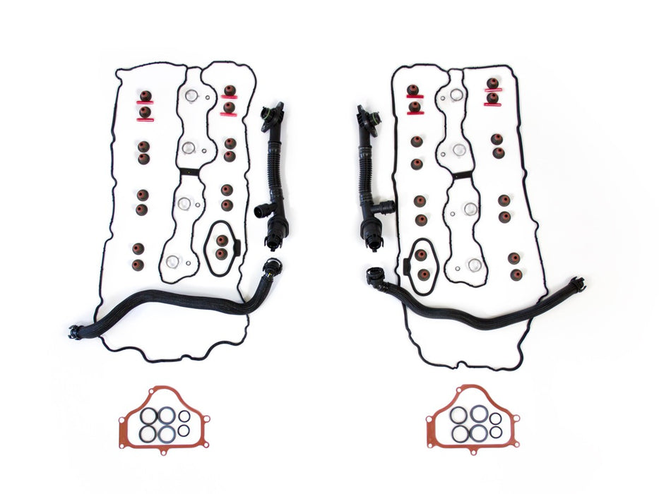
- All of the parts you need to do a complete valve stem seal replacement on BMW N63 engines. This kit includes:
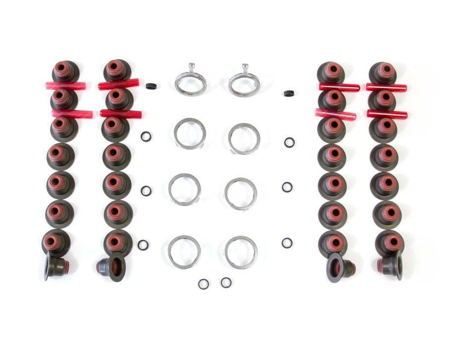
32 Elring valve stem seals
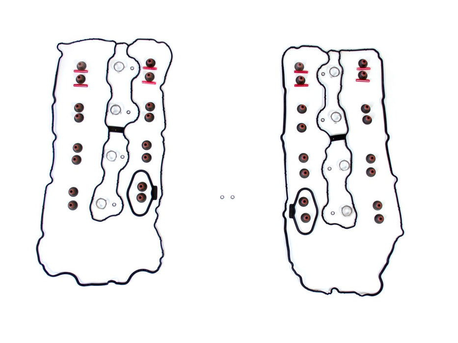
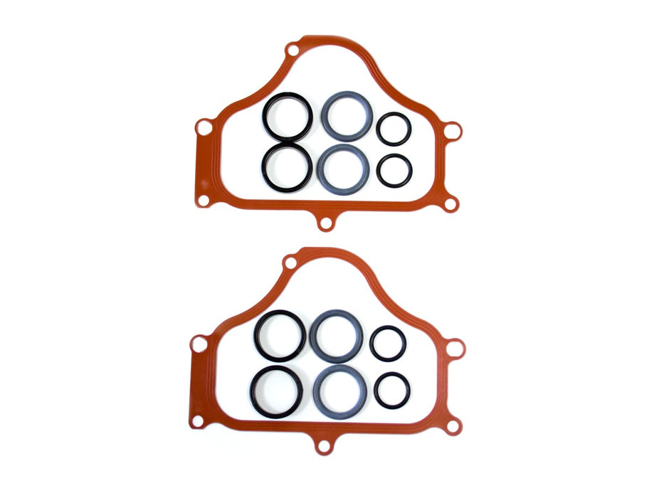
Valve covers gaskets & high-pressure pump seal gaskets - left & right side
Ten injector seals (Two Extra Seals Included)
Eight injector coupling seals
Front timing cover gaskets
2 solenoid seal – Sets inner and outer
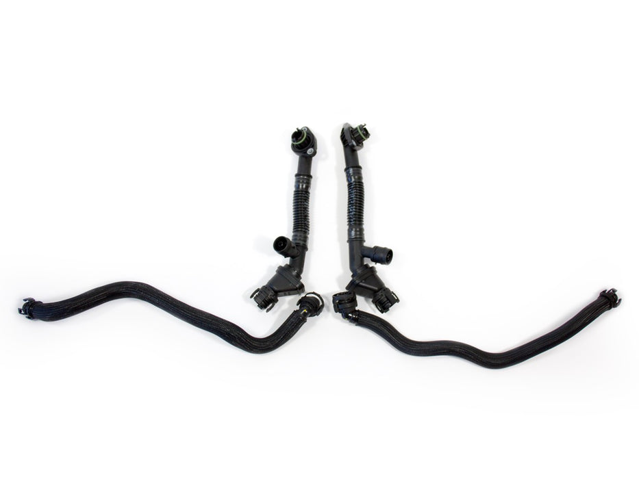
PCV valve – Left and Right
PCV hoses – Left and Right
- This complete set includes oil separators and PCV hoses which are notoriously brittle, so your repair job isn’t put on hold due to broken parts.
- Please Note: This does not include the N63 Valve Stem Seal Tool Kit. We recommend purchasing the N63 Tool Kit to make removing and replacing valve stem seals quicker and easier. Click here to buy.
Ordering from Europe? Click here to buy from our European distributor KOED
Specifications
Models This Product Fits
- N63 Engines
Parts Included With This Kit
| Quantity | 32 |
|---|---|
| Part # | 11-34-0-039-494 |
| Description | Valve Stem Seals |
| Quantity | 8 |
|---|---|
| Part # | 13-53-7-564-751 |
| Description | Injector Coupling Seal |
| Quantity | 10 |
|---|---|
| Part # | 13-53-7-584-315 |
| Description | Fuel Injector Seal |
| Quantity | 1 |
|---|---|
| Part # | 11-12-7-566-288 |
| Description | Valve Cover Gasket Right |
| Quantity | 1 |
|---|---|
| Part # | 11-12-7-566-289 |
| Description | Valve Cover Gasket Left |
| Quantity | 1 |
|---|---|
| Part # | 11-12-7-566-290 |
| Description | High Pressure Pump Gasket L & R |
| Quantity | 2 |
|---|---|
| Part # | 11-12-7-566-281 |
| Description | Timing Cover Gasket |
| Quantity | 4 |
|---|---|
| Part # | 11-36-7-548-459 |
| Description | Solenoid Seals Outer |
| Quantity | 4 |
|---|---|
| Part # | 11-36-7-561-852 |
| Description | Solenoid Seal Inner |
| Quantity | 1 |
|---|---|
| Part # | 11-15-7-646-086 |
| Description | PCV Valve Right |
| Quantity | 1 |
|---|---|
| Part # | 11-15-7-646-087 |
| Description | PCV Valve Left |
| Quantity | 1 |
|---|---|
| Part # | 11-15-7-575-640 |
| Description | PCV Hose Bank 1 |
| Quantity | 1 |
|---|---|
| Part # | 11-15-7-575-641 |
| Description | PCV Hose Bank 2 |
| Quantity | 2 |
|---|---|
| Part # | 11-12-8-636-401 |
| Description | Profile Gasket |
Total $573.19